
1.0 |
RAW WATER |
Reverse Osmosis Water System (SOP) is that water, which is obtained from well or any reservoir. Reverse Osmosis Water System (SOP) contains minerals, salts chlorides, sulfates, calcium & magnesium etc. Microbial count of raw water, which may be used for drinking, is 500CFU/ml. The ingredients present in this water may be incompatible with our medicine and can disturb the stability of product so, purification of this water is required.
2.0 |
PURIFIED WATER |
Purified water is that water which is obtained by distillation, ion exchange treatment, reverse osmosis or other suitable process from suitable potable water. It contains no added substances Purified water is required for manufacturing of quality medicine in Searle Pakistan Limited.
3.0 |
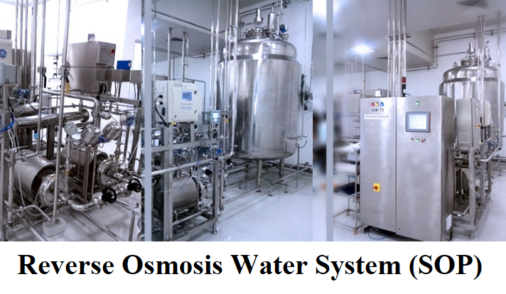
DESCRIPTION OF REVERSE OSMOSIS WATER SYSTEM |
In Searle Pakistan Limited., water treatment plant consists of reverse osmosis system.
3.1 Reverse osmosis process
A plant cell is a semi-permeable (water flows through the membrane but salts don’t) membrane with the living stuff on the inside in a salt solution. Water is drawn into the cell from the outside because pure water will move across a semi-permeable membrane to dilute the higher concentration of salt on the inside. This Reverse Osmosis Water System (SOP) is how water is drawn in from the ground when you water your plants. If you salt your plants (over fertilize or spill some salt on the grass), the plant will wilt because the salt concentration on the outside of the cell is higher than the inside and water then moves across the membrane from the inside to the outside.
To reverse this process, you must overcome the osmotic pressure equilibrium across the membrane because the flow is naturally from dilute to concentrate side. We want more pure water so we must increase the salt content in the cell (concentrate side of the membrane). To do this we increase the pressure on the salty side of the membrane and force the water across. The amount of pressure is determined by the salt concentration. As we force water out, the salt concentration increases requiring even greater pressure to get more pure water.
3.2 Pre-treatment of R/O system
System also involves U.V light for bacterial killing as shown in the figure. These lights should be switched on and lights connection should be in contact with the electric supply. Cascade of the semi- permeable membrane should not show any leakage at their ends and the piping of whole R/O plant should be firmly connected with respective places.
By checking these simple parameters of preventive maintenance, it will be easy to maintain R/O system. R/O system eliminates the repeated charging of D/I plant. The rejection of water through membrane should be less to increase the life of membrane of R/O plant.
3.3 Plugging of membrane
To avoid plugging of membrane, in coming water is filtered to remove particulate and colloidal substances. There are two ways to reduce the chance of plugging. Chemicals can be added to the feed stream that keeps the hardness from precipitating. This is simple metered directly into the pipe feeding the R/O plant.
Second way is to remove the hardness with water softener. It will reduce the chance of plugging.
If there is plugging of membrane, we will contact our consultant Mr. Iqbal to solve this problem.
3.4 Membrane life
R/O membranes can be used for 3years, if properly maintained.
3.5 Microbial control of R/O system
The water of reverse osmosis system is optionally passed through ultra violet lights, which kill the bacteria in the system. All tanks should be black or opaque to prevent growth of algae.
4.0 |
WATER TREATMENT SYSTEM |
4.1 Well
In the well iron pipes are present in the under ground boring line. This pipeline goes to a depth of 450ft.
4.2 Turbine
On the ground level a turbine is fitted to the under ground pipeline. This turbine takes the water from a depth of 450ft. and then supplies to the over head tank. Right after the turbine there is a sampling point.
4.3 Overhead Water Tank
From the well raw water is stored in overhead tank. This tank is cemented and covered. This raw water is then supplied to water treatment plant. The capacity of tank is about 5,000 liters. The tank is at the height of 20 ft. from ground level. Water from its tank comes down through the iron pipe. There is a sampling point after the over head tank. The pipes which supply the water to this tank and takes the water away from tank are iron made and 4½ inches in diameter. In this tank one outlet pipe for the over flow of water is also provided. This pipe is kept closed under normal conditions except when the over flow of water is there.
4.4 Feed Pressure Pump
To create the required system pressure,
Specification:
Type |
Mono Block Imported |
Performance type |
Propeller |
| Pump material | S.S |
| Max. Pressure | 150 Psi |
| Pump Motor Power | 1-HP |
| In-let / out-let Size | 3/4”X ¾ ” |
| Electric Supply | single-phase supply |
It provides pressurized pumping of water. Whenever R/O plant is in operation, we have to check the pump pressure. It should be 20 psi – 30psi and flow of water through R/O plant should be 1.5gpm. The pressure required is depended on the concentration of the salt solution on the reject (concentrate) side of the membrane running a system at 1100mmp on the concentrate side requires over 200psi. Sea water systems at 33,000 + ppm run at 800 + psi. Water over here contains 700 – 1000 ppm total dissolve salts so we need the pressure between 20 psi – 30 psi.
4.5 Sand Filter:
Consist of re-enforced Fiber glass vessel of, 54” x 10”dia with 3 type gravel filtration material beds, with single lever mutiports valve back wash system. The sand filter removes suspended particles down to 15 micron, e.g. sand, dust, rust, slit etc according to WHO standards.
Specification:
| Vessel Size | 54” x 10” Dia |
| Vessel material | Fiber Glass Imported |
| Filling material | 3-Beds,Quartz sand- 100 Kg |
| Fittings | PVC imported |
| Inlet | 3/4” |
| Outlet | 3/4” |
| Back wash Time | 10- 15 Minutes |
| Back wash System | Single lever Mutiports valve (imported) |
| Standard | WHO / AAMI |
4.6 Carbon Filter:
Consist of re-enforced fiber glass vessel of 54” X 10” Dia with 2 type gravel filtration material beds and coconut-based activated carbon, with back wash system.
The carbon filter removes / adsorbs organic chemicals, chlorine, and sulpher pesticides, herbicides etc. After the charcoal bed the water is filled through a bed of gravels and improves the color and taste of water according to WHO
Standards.
Specification:
| Vessel size | 54” x 10” Dia |
| Vessel material | Fiber Glass |
| Filling material | 1Bed, Filtration Gravels, 20 Kg |
| Fittings | PVC imported |
| Inlet | 3/4” |
| Outlet | 3/4” |
| Media | 1 bed Activated Carbon |
| Back wash Time | 10-15 Minutes |
| Back wash System | Single lever Mutiports valve (imported) |
| Standard | WHO / AAMI |
4.7 Water Polisher:
Consist of 20-inch Jumbo housing with polypropylene cartridge. It will remove the residual carbon and suspended particles finally down to 01(one) micron. After passing through 01 micron post treatment filter water gives Sprinkling look
Specification:
| Housing size | 20” Jumbo |
| Housing material | Polypropylene |
| Cartridge material | Polypropylene |
| Fittings | PVC imported |
| Fitting size | 3/4” |
| Housing Quantity | One No. |
| Standard | WHO / AAMI |
4.8 Hardness Stabilizing System:
To remove harmful hardness a anti scaling chemical will be injected at a constant / required flow rate.
Note: required chemical will be provided by the client!!!
Specification:
Performance type |
Stroke |
| Make | Imported, Italy |
| Electric Supply | single-phase supply |
4.9 PRIMARY REVERSE OSMOSIS:
Reverse Osmosis, originally designed to purify or desalinate seawater is a process where feed water flows over a membrane, while Pressure forces pure water through the membrane. The impurities are rejected at the membrane surface and are concentrated in the rejected water stream. The water, which is forced through the membrane, is purified and constitutes the clean water stream. In general, water treated by R.O.is feed from 90-95% of the dissolved solids present in the feed water. Non-ionized solutes, bacteria, viruses and pyrogens with a molecular weight larger than 200 Dalton are also removed.
These systems are frequently used in the Pharmaceutical. Hospitals, Textile chemical process and mineral water plants
Specifications:
| System Feed Pressure | 2.5 bar |
| System Maximum Operating Pressure | 150 psi |
| Membrane Size | 40 inch X 4 inch |
| Quantity of Membrane. | 02 Nos. |
| Type of pump | Multistage SS |
| Type of membrane material | Polyamide. |
| Membrane casing material | S.S |
| Minimum required pressure for the pump | 10-12bar |
| Electric supply | Three-phase |
| Chemical Disinfection facility | Yes Port available |
| Product Out Put | 9- 10 Liter/ minute |
| Pre Filter Housing length | 10” standard |
| Housing Material | P.P Imported |
| Cartridge Filtration rating | 01 Micron nominal |
4.10. Product Storage Tank:
Used for storage of primary R.O product water.
Specifications:
| Size/ Capacity | 250Liter |
| Material | P.P |
| To Be Provided by | Administration of Searle Pakistan Limited |
| Fittings | PVC imported |
| Fitting size | 3/4 ” |
| Colour | Crystal |
4.11. BOOSTER PUMP:
To create the required system pressure & Flow.
Specification:
Type |
Mono Block |
| Performance type | Propeller |
| Pump material | Stainless steel |
| Electric supply | 220 volt single phase |
| Inlet | 3/4 ” |
| Outlet | 3/4” |
4.12 SECONARY REVERSE OSMOSIS:
Specifications:
ALL SAME AS PRIMARY R.O
4.13. Product Storage Tank:
Used for storage of primary R.O product water.
Specifications:
| Size/ Capacity | 2000 Liter |
| Material | S.S 316-L |
| To Be Provided by | Administration of Searle Pakistan Limited |
| Fittings | PVC imported |
| Fitting size | 3/4 ” |
4.13. BOOSTER PUMP:
To create the required system pressure & Flow.
Specification:
Type |
Mono Block |
| Performance type | Propeller |
| Pump material | Stainless steel |
| Electric supply | 220 volt single phase |
| Inlet | 3/4 ” |
| Outlet | 3/4” |
4.14 . Ultraviolet Sterilizers:
Complete system. Consisting of compact unit of 3 x36” UV lamps. UV sterilizer kills or inhibits water borne bacteria and viruses, which are the main cause of Jaundice, Typhoid, and Dysentery etc.
Specifications:
| Size of UV tube | 36 inches |
| Quantity of Tubes | 03 Nos. |
| Intensity | UV253.7nm.UW/cm |
| Working life of lamps | 3000 hours |
| Output | 32 W |
| Lamp current | 0.31 A |
| Casing material | S.S,316-L ( compact casing ) |
| Minimum required pressure for the pump | 10-12bar |
4.7.3 Rejection of Water
Quantity of waste water is 50%, which means 50% (12-13 LPM) of water is rejected by the membrane.
Reject water is discharged directly to drain. Usually the TDS is less than 100 ppm and there are no contaminants. If a system is used to recycle some water after a plating application, monitoring of the reject may be necessary.
4.8 Flow Meter # 1 & 2 (Control 1st two membranes)
Flow meters used are manufactured by King Instruments Co. USA. There range is 1 – 20 LPM. When reverse osmosis system is in working condition then the flow of water through flow meter # 1 & 2 is 12 – 13LPM. Flow meter # 1 indicates the flow of water which passes through the R/O membrane and flow meter # 2 indicates the flow of waste water. If there is any decrease in the flow of water shown by the flow meters, then we have to check the membrane. There might be plugging of reverse osmosis membrane. Then cleaning of membrane is required. Cleaning of membrane is mentioned.
4.9 Flow Meter # 3 & 4 (Control 1st last two membranes)
Flow meters used are manufactured by King Instruments Co. USA. There range is 1 – 20 LPM. When reverse osmosis system is in working condition then the flow of water through flow meter # 1 & 2 is 12 – 13LPM. Flow meter # 1 indicates the flow of water which passes through the R/O membrane and flow meter # 2 indicates the flow of waste water. If there is any decrease in the flow of water shown by the flow meters, then we have to check the membrane. There might be plugging of reverse osmosis membrane. Then cleaning of membrane is required. Cleaning of membrane is mentioned.
5.0 |
VALIDATION & TESTING OF WATER SYSTEM |
The validation and frequent monitoring of the water quality is also done. The validation plan is given below:
| Water Sampling Point | Place | Tests and Frequency | Purpose |
| SP-1 | Between Tank and Sand Filter | Chemical and microbiological. Fortnightly | To prove the chemical quality of the well water and the change of the microbial Quality in the Tank |
| SP-2 | After Hardness Stabilizing System (Anti-scaling System) | Chemical:Twice a week | To prove the effect of the Hardness stabilizing system |
| SP 3 | Primary storage tank | Chemical:Twice a week | To prove the efficacy of 1st two membranes. |
| SP-4 | After 2nd R/O and UV lights | Chemical daily | To check the R/O system performance |
| SP-5 | After Passing through UV lights | Microbiological once in a week | To check the performance of UV lights. |
| SP-6 | Water Storage Tank | Chemical Daily or before going to use and Microbiological Once a week | To check the storage water |
6.0 |
CERTIFICATE OF ANALYSIS |
| S. No. | TEST APPLIED | SPECIFICATION | RESULTS |
| 1 | Description | Clear, colorless, odorless liquid | |
| 2 | pH | 5.0 – 7.0 | |
| 3 | Acidity & Alkalinity | Passes test | |
| 4 | Chlorides | Passes test | |
| 5 | Total hardness | < 5 ppm | |
| 6 | Calcium | Passes test | |
| 7 | Ammonia | Passes test | |
| 8 | Nitrate | Passes test | |
| 9 | Nitrite | Passes test | |
| 10 | Read Oxidizable sub. | Passes test | |
| 11 | Heavy Metals | Passes test | |
| 12 | Sulfates | Passes test | |
| 13 | TDS/Conductivity | NMT 5ppm | |
| Microbial Tests | |||
| 14 | Total Viable Count | NMT 100 CFU/ml | |
| 15 | E. Coli | Absent | |
| 16 | Salmonella sp. | Absent | |
| 17 | Pseudomonas aeroginosa | Absent |
Remarks:
Analyst: Microbiologist: Q.C. Manager: